Top

From Wireframes to Code, Part II

February 21, 2011

In Part I of this series, I discussed two different approaches to wireframing:

  • separated code approach—in which the artifact you create to communicate your design is separate from the production code
  • integrated code approach—in which you use the same artifact for design and production code—creating code directly from wireframes

I examined the pros and cons of each of these approaches, as well as their impacts on the design process. In Part II, I’ll first explore what it would be like to instead go from code to wireframes. Then, for those of you who want to try employing a process flow that progresses from wireframes to code, I’ll discuss what types of prototyping tools would be best for your projects and how their use would impact your product development process.

Champion Advertisement
Continue Reading…

What About Going from Code to Wireframes?

During a break from a long wireframing session, I was watching a snowstorm outside when the irony struck me. I had been thinking about how useful some particular wireframes had been in keeping our group together and assisting us in making design decisions. In fact, I could think of no other medium capable of both communicating design changes and facilitating the discussion that had kept the project moving along.

These wireframes had served us faithfully from the beginning—morphing from whiteboard to gray-scale outlines to the current set of colored, high-fidelity “infosthetics.” They were actually a composite of three different types of wireframes: garden-variety Visio wireframes, cannibalized screenshots of a prototype with Visio overlays, and screenshots of an actual second-level page. They even included a prototype from a usability test, in which we had embedded interactive wireframes.

The irony I felt had come from that last set of wireframes, which we had created out of production code. It occurred to me that this was really the exact opposite of what I had written in Part I of this series. Instead of going from wireframes to code, I had actually gone in reverse, from production code to wireframes!

After putting out the bonfire I had lit with the notes I’d planned to use for Part II, I pondered the meaning of all this. Would I need to redraw the flows from Part I? What impact would this new approach have on the process of creating code?

Lessons Learned

This episode taught me two important things about our work. First, real life is messy and chaotic. Software dependencies change, people move off projects, goals change. It’s one thing to draw flowcharts and diagrams and discuss the theories of proper information flow. But they don’t always reflect the vagaries of real life. I could draw out the process I’ve used on most of my projects with tidy linear arrows and boxes. But the bottom line is: you and your process have to be flexible and agile enough to adapt to the needs of any project.

Which led me to my second lesson: Although all of our theories really do help us think about our work in the proper way, at the end of the day, you really need to do whatever it takes to get your message across and move your team forward. To quote former Oakland Raiders head coach Art Shell, “Just win, baby.” Our goal is not to create perfect, pristine diagrams that adhere perfectly to design documentation guidelines. Our goal is to create a common idea space that facilitates team communication and collaboration. The bottom line is that your diagramming software, wireframes, and prototypes are all simply tools in your toolbox.

One final note on this topic: One reader who commented on Part I of this series posted an interesting and relevant link. Jussi Pasanen has created a very interesting application called Wirify, which actually does convert production code to wireframes. Figure 1 shows before and after images.

Figure 1—The actual page and a Wirify wireframe of CNN.com
The actual page and a Wirify wireframe of CNN.com

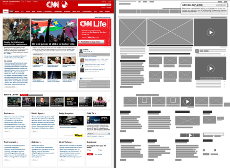
Wirify allows you to convert any Web page into a wireframe with the simple click of a browser toolbar button. Since I had just finished writing this first section of Part II, I got pretty excited about this application!

The existence of Wirify does prompt this process question: When in the development process would one use an application like this? Perhaps you could use it to establish a baseline when progressing from one version of a site to another? Or for comparative purposes? I’m hoping Jussi and others will weigh in with ideas for how to use this innovative application. Thanks for sharing it, Jussi.

From Wireframes to Code: Considering the Tools

Now, let’s focus on the integrated code approach and look at the technologies that are available for those who want to use it, then delve more deeply into the characteristics of these tools. How do you start? What are the best tools? What should you keep an eye out for?
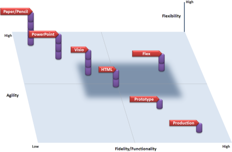
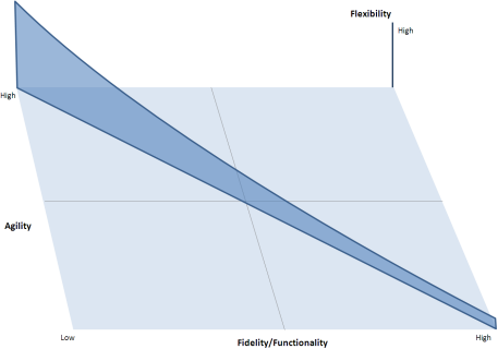
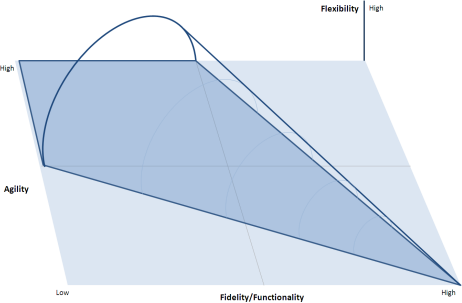
Tradeoffs

When considering what tool to use for creating code, here are some factors to consider:

  • learning curve—Some tools are just easier to use than others. If you’re an information architect with little programming experience, you may want to choose a tool that emphasizes ease of development. But keep in mind that this ease may come at the cost of more unwanted code.
  • development curve—Even if you do have coding skills, it just takes longer to create code with some tools than others. For example, you can use Flash to produce some very interactive prototypes, but creating those prototypes can be very time consuming.
  • coding interaction—Bottom line: You don’t get anything for free. You can code interactions from scratch, which gives you a richly interactive, but time-consuming-to-create prototype, or you can have agility and create a quick-and-dirty prototype whose functionality you’ll have to recode later. There is no perfect solution—yet.

Constraints

There are many viable prototyping tools. Which one should you choose? Here are several types of constraints that can help you narrow down your choice, including the following:

  • technology boundaries—These are probably the most important and restrictive constraints: the tool forcing the project to adapt to a technology or environment. After all, we are talking about creating production code from wireframes. An application that simply doesn’t let you create production code that’s appropriate for your context is a show-stopper.
  • technology dependencies—All applications have technology dependencies. And these have a tendency to change, which can come back to bite you later in the development process. I’ve heard stories of projects where software dependencies changed near the end of the development cycle. Using the integrated code approach, in this case, turned out very badly, because the team was forced to step back to square one. While your team might be able to handle this problem easily when using the separated code approach—where wireframes and code are independent of one another—if you’re too far along in your development process using the integrated code approach, starting from scratch could be a serious issue.
  • limitations of the coder’s ability—Knowing your own and your team’s limitations can help in narrowing down the selection process.

Capabilities: A Continuum

Certain dimensions of a software tool’s capabilities interact with one another, so they may also limit what tools are available to you. Consider the following three dimensions of wireframing tools, which Figure 2 represents in a graph:

  • flexibility—How broad are a tool’s applications? Paper-and-pencil sketches apply in all situations; a specialized Delphi prototype may apply in only one.
  • agility—How well does a tool facilitate rapid design iterations? A complex or cumbersome tool can hold back your progress.
  • fidelity of functionality—How close can your initial wireframes come to the final product’s functionally? How many of its interactions can you add to the prototype? While it’s almost impossible to add functionality to a paper prototype—although designers have simulated interactivity—it’s definitely possible with a C++ prototype.
Figure 2—Wireframing tools’ capabilities
Wireframing tools' capabilities

This graph depicts the characteristics of a representative sampling of wireframing tools in three dimensions—for example, Visio represents all wireframing tools that let you create wireframes with limited functionality, including Balsamiq and OmniGraffle Professional. The X axis shows fidelity and functionality; the Y axis, agility; and the vertical Z axis, applicability. The gray area in the middle represents the sweet spot, encompassing the tools most commonly in use for wireframing. These tools provide the best balance of flexibility and agility for a given level of functionality.

As the graph shows, paper-and-pencil sketches are most agile and flexible, but also have the lowest fidelity. On the other hand, near production-quality software prototypes have low agility, but almost complete functionality.

I’ve oversimplified the graph in Figure 2 to demonstrate a principle: the inverse relationship between agility and functionality. Plus, by definition, an increase in functionality decreases the degrees of freedom for a design. This makes perfect sense, because you have to program the functionality somehow or at least think about the additional interactivity.

In this graph, the height of each column depicts a tool’s flexibility, or applicability. For example, you could use paper-and-pencil sketches for any project, but a Delphi prototype might be applicable to only a specific project, in a specific environment. Notice how flexibility also decreases as interactivity, or functionality, increases. Thus, a three-way interaction exists between these three different dimensions—that is, both agility and flexibility decrease as you add richer functionality to a prototype, creating the technology slide shown in Figure 3.

Figure 3—The technology slide
The technology slide

In my opinion, the one exception to this rule that there is an inverse relationship between agility and flexibility versus functionality seems to be Flex. In the past, I’ve successfully used Flex to create production code, and it was extremely agile. It did score lower on the applicability scale—somewhere between HTML and Software Prototype. There are many other tools out there that don’t appear on this chart. However, in general, I think the basic principle holds up: there is an inverse relationship between agility and flexibility versus functionality. You can’t get something for nothing.

As I created these graphs, I wondered what a graph of a technology’s effect on an idea space would look like. If you think of the size of an idea space in terms of the degrees of freedom that are available for different thoughts—the larger an idea space, the more thoughts it can simultaneously accommodate—the graph of a technology’s effect on an idea space would look similar to the technology slide, as shown in Figure 4.

Figure 4—Graph of a technology’s effect on an idea space
Graph of a technology's effect on an idea space

As the graph moves from the upper left, or high agility, to the lower right, or high fidelity and functionality, the size of the idea space shrinks—meaning you would have a lower degree of design freedom. For example, you could design anything with paper and pencil—a rocket, a dinosaur, a time machine—but as you add functionality, you become restricted by the technology. (Unless you think you actually can prototype and build that time machine you drew on the back of a napkin!) So, there is a direct correlation between the size of the idea space and the flexibility of the design medium.

The Perfect Prototyping Tool

Keeping all of these factors in mind, what would the perfect prototyping tool look like? Its driving philosophy would be to maximize the idea space while enabling you to create clean, final code. So, if we could wave a magic wand and create the perfect tool, it would have the following characteristics:

  • completely usable by designers
  • completely usable by coders
  • agile
  • supports different levels of fidelity—for example, switching from Balsamiq-like, low-fidelity drawings to production-ready user interfaces, including reskinning
  • creates clean code
  • lets you switch from a design mode to a develop mode with the press of a button
  • supports a wide variety of technologies, including the Web, C++, Java, and XML

That’s my wish list. I’m hoping some of you will add your wishes through comments. Who knows? Perhaps one of the prototyping-tool companies might take notice.

Impact on the Development Process

Finally, what impact would this perfect prototyping tool have on a project’s software development process? Well, let’s first assume our hypothetical project team includes both a designer and a coder, and they would both use the same tool. The designer would create wireframes, have stakeholders review them, and refine them. Once the design became solid, the designer would create to exact specifications what would become the product’s final user interface. The designer would then hand the prototype off to the developer, who would put all the final code in place. Voilà—all done.

Slight plug here. For my money, Flex really seems to approach what I would call the perfect prototyping tool. The only two characteristics from my wish list that it lacks are different levels of fidelity and support for a wide variety of technologies. The latter deficiency is something of a show-stopper for most product teams, because Flex requires the use of Flash. I’ve also heard from some that it creates dirty code, although I have not yet seen this on any of my own projects.

This wireframes-to-code scenario poses a host of questions: How would you handle design rework later in the development process? Would there be a tendency to jump right to code or undervalue the role of the designer? I would love to hear the thoughts of readers on this.

What’s Next?

We’ve now covered much of the theory and process behind creating code from wireframes—and vice versa. In the next part of this series, we’ll take a look at some actual code to identify the things to look out for when going from wireframes to code.

Now that you’ve read Part II, I hope you’ll share your thoughts on this approach in the comments. Stay tuned! In Part III of this series, which I’ll coauthor with Martin Lambert, I’ll analyze some actual code we’ve created using a number of wireframing tools. 

Senior Design Analyst at the National Board of Medical Examiners (NBME)

Philadelphia, Pennsylvania, USA

Bill SchmidtA practicing usability engineer since 1995, Bill is currently working with the National Board of Medical Examiners, where he wears multiple hats as usability engineer, interaction designer, and visual designer. He has also worked with a number of Fortune 500 companies in the financial, pharmaceutical, energy, and manufacturing industries, for clients such as Microsoft, Lincoln Financial, BP, Comcast, Wyeth, Astra Zeneca, and power supplier for the UK, National Grid. Working with clients in the energy sector, Bill evaluated and designed user interfaces for electricity and natural-gas control rooms. He spent 10 years working on complex command-and-control systems for the U.S. Air Force and Navy—including AWACS, NORAD, and AEGIS radar systems.  Read More

Other Articles on Communicating Design

New on UXmatters